- Extend piston to the top stop ring and inspect the full length of the piston. Remove all burrs, scores, or rusty spots by lightly sanding before removing the old packing. Also, job numbers stenciled on top of piston and other sharp ridges should be removed. Marks should be sanded and smoothed before removing old packing.
- Make sure the elevator car is securely landed on substantial supports or jacks to support the full weight of the elevator car, keeping the platform level. Then, pull the main line switch. Lock out and tag out.
- Remove bolts or clamps from the piston to the platen plate and lower the piston into the cylinder to bottom-out position by opening the manual lowering valve.
- Close the shut-off valve and open the bleeder valve before removing all packing.
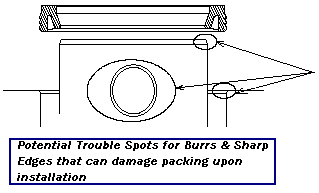 The entire head can usually be removed for close inspection and clean up; however, the packing can be removed by: removing the gland and using packing tools. Lantern, backup, and wear ring are usually drilled for two (2) 1/8” pull hole for easy removal with screw puller or a No. 8 screw. Make sure the packing tools do not scratch or score the plunger or the I.D. of the packing box. It is equally important for both surfaces to be clean and smooth. Should the bore of the packing box be damaged from previous re-packing, head should be removed and smoothed with small file or emery cloth.
-
For packing boxes that can be repacked while in place: Remove the oil from the seal cavity. Slip the pressure-balance seal over the plunger with its hollow section downward. To prevent the outside lips of the seal from damage during installation, lift one side of the seal and twist it enough to allow the other side of the seal to enter the packing box. Using a wood wedge, press inwardly, feeding the seal lips into the packing box while pressing downward until the lips are inside the packing box. Always install the seals with ribs toward the fluid pressure. Never stack one seal upon another seal. Always use a lantern or a lantern-bearing combination between seals.
-
For jacks that require removal from the cylinder in order to repack (Bench-Pack Head):
-
Remove the head and place head upside down. Always install seals with ribs toward the fluid pressure. Never stack one seal upon another seal. Always use a lantern or a lantern-bearing combination between seals.
-
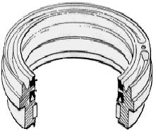
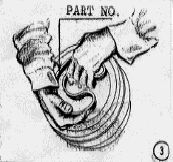
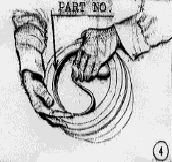
Snap in place groove bench-pack heads. Remove old seals and bearings being careful not to scratch the I.D. of the seal groove. Carefully fold the seal into an upside down U-shape, with the part number at the bottom of the U-shape. The part number must not be in any of the sharp bends. Refer to Diagram 1.
| Diagram 1: Snap in Groove Bench-Pack Heads |
| (It is recommended that, for installation ease, the seal be installed before the wiper ring.)
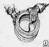
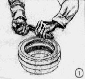
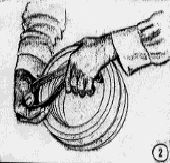
NOTE!: WHEN BENDING PACKING, PART NUMBER MOLDED IN TOP OF THE PACKING MUST NOT BE IN SHARP BEND. SEE PICTURES 3 AND 4 BELOW.
- Position packing gland on flat surface with wiper ring groove up. Grasp packing seal with both hands and compress as shown.
- Place end of compressed seal into packing seal groove. Hold end of seal in groove and bend seal to match contour of packing gland.
- Force seal into a semicircle and press seal down into packing seal groove.
- With the seal partially in place, slowly release grip to allow seal to expand into seal groove.
- As the seal expands, press it into ring groove securely to insure proper sealing
INSTALL WIPER RING IN WIPER RING GROOVE USING THE SAME BASIC PROCEDURE OUTLINED IN STEPS 1 THRU 5
|
|
|
-
When changing packing on Holless Hydraulics, size the landing block to provide approximately 5” clearance for the removal and the replacement of the packing.
-
Sand both plungers from top to bottom
-
Run elevator down to bottom floor. Land elevator where you have five inch between cross head and plunger. Open manual lowering valve. Let the plunger all the way down.
-
Pull main line. Lock out and tag out.
-
Replace the gland ring and bolt down tight.
-
Open the shut-off valve, close the manual lowering valve, turn on the main line switch and “jog” the motor to pressurize the system. Then, remove the air through the bleeder. Close the bleeder when oil comes out. Carefully “jog” the motor to raise piston up to support the car. Fasten piston to platen and remove supports or jacks.
-
Adjust the control valve as needed to compensate for the new packing as per the valve manufacturer’s instructions.
Note: The procedures suggested above do not take precedence over the elevator manufacturer’s instructions.
Important
Note: The installation of replacement parts or components on elevator equipment should only be performed by a trained elevator technician who is familiar with the operation and control of the system being repaired, as well as the parts being installed. When installing replacement parts or components, follow the instructions provided by the manufacturer of the elevator equipment.
Before attempting to repair or install replacement parts or components on elevator equipment, all safety precautions recommended by the equipment manufacturer should be followed.
Warning: Failure to observe proper safety precautions and/or to follow recommended installation procedures may cause improper or unsafe installation of parts and may endanger the installer, the public, and the equipment.
In addition to following all manufacturer safety precautions, you must follow all local, state, and federal safety regulations and all elevator safety codes are applicable. Gorman Co., Inc. has no liability for the failure of those performing installations, repairs, or replacements to follow manufacturer’s standards and specifications, and for the failure to observe and follow all safety precautions.
Gorman Co., Inc. has no liability for the failure of those performing installations, repairs, or replacements to properly perform such installations, repairs, or replacements.